- Authors:
- Sébastien Mosser
- Philippe Collet
- Mireille Blay-Fornarino
The modelling community is aware of issues related to the teaching of modeling. Difficulties with the abstraction and hindsight needed in metamodeling, or with the heaviness of the available tools such as the Eclipse Modeling Framework (EMF), are typical examples. Such issues make it very challenging to transfer Model-Driven Engineering (MDE) and Domain Specific Languages (DSLs) to students.
To tackle this challenge, Batory et al reported an experiment made at the University of Texas at Austin that uses database concepts as a technological background to teach MDE. This experiment is decisive as it makes explicit that it is possible to teach MDE without introducing the complexity of tools such as the EMF. However, it uses classical MDE examples (e.g., class-based structural meta-models, finite state machines), with trivial applications such as Java code generation. We tried in 2008 to introduce in our course contents a set of very similar examples. In addition to the complexity of exploiting the EMF (as spotted by Batory et al), students pointed out the artificial dimension of such examples.
Page and Rose published a tribune entitled “Lies, Damned Lies and UML2Java” in the Journal of Object Technology, stating that “It would be much more interesting to read about MDE scenarios that don’t involve the infamous UML2Java transformation”. Based on this assumption we introduced in 2012 a case study based on the Internet of Things, where students had to model sensor dashboards. We exploited the Sensapp platform, and students were asked to provide a meta-model and the associated tooling to plug data collected from sensors by Sensapp into graphical widgets (targeting HTML and Javascript im- plementations). In the yearly feedback, students were still complaining about the EMF, but appreciated the theme. They emphasized the practical dimension of the assignment, and stated that seeing a model being transformed into a graphical dashboard was more enjoyable that into plain Java code. However, the main negative feedback was the same: they did not see the real benefit of using models in this context. The use case was still too trivial, and it was simpler for them to program a dashboard in plain Javascript than to follow an MDE approach.
As a consequence, we proposed in Fall 2013 a new version of this course, based on a DSL named ArduinoML. Our objectives were threefold: (i) to emphasize the benefits of using models by exploiting a non-trivial and realistic case study, (ii) to support practical lab sessions associated to the course and (iii) to provide a project description abstract enough to decouple it from tools.
The ArduinoML project uses as its initial assumption the existing gap between (i) a piece of software implemented on top of the Internet of Things and (ii) the initial intention of the user.
We consider as an illustrating use case the following scenario: Alice owns a button (a sensor) and a LED (an actuator). She wants to connect these two things together in order to switch on the LED when the button is pushed, and switch it off when the button is pressed again.
The code necessary to implement this scenario on top of an Arduino micro-controller is the following (see Arduino tutorials for more details)
int BUTTON = 9;
int LED = 12;

void setup() {
  pinMode(BUTTON, INPUT);
  pinMode(LED,    OUTPUT);
}

int state = LOW; int prev = HIGH;
long time = 0; long debounce = 200;

void loop() {
  int reading = digitalRead(BUTTON);
  if (reading == HIGH && prev == LOW && millis() - time > debounce) {
    if (state == HIGH) { state = LOW; } else { state = HIGH; }
    time = millis();
  }
  digitalWrite(LED, state);
  prev = reading;
}
The ArduinoML language support the user by reifying the concepts hidden in the previsouly described scenario:
- Structure: Alice was talking about electronic
Bricks, asSensors andActuators. - Behavior: Alice had a state-machine in mind when she described her application. A
State"off" where the led is switched off, and another one where the led is switched on. Going from one state to the other is driven by aTransition, associated to the value available on a sensor.
The following figure describes as an UML class diagram this meta-model, where structural concepts are depicted in orange and behavioral ones in green.
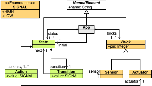
Remark: the fact that a state contains a single transition is not a bug, it is a simplification to ease the code generation. In the context of our DSL engineering course, it is one of the available extensions to support multiple transitions.
The switch example previously described can be modelled as the following using this meta-model:
- The button is a
Sensor, bound topin9 andnamed "button"; - The led is an
Actuator, bound topin12 andnamed "led"; - The application is an
App, withname"Switch!";- It contains the button and the led as its
bricks; - It contains to
States (withnames"on" and "off"), stored instates; - It uses "off" as its
initialstate;
- It contains the button and the led as its
- The "on" state:
- contains an
Actionthat sendsHIGHto the led - owns a
Transitionwherenextis "off", triggered when the button isHIGH
- contains an
- The "off" state:
- contains an
Actionthat sendsLOWto the led - owns a
Transitionwherenextis "on", triggered when the button isHIGH
- contains an
Based on a model conform to the previously described meta-model, one can expect as benefit of using the ArduinoML language to automatically generate the Wiring code to be used on the micro-controller.
Using the Wiring library, the structural part of the meta-model is mapped to the implementation of the setup() function. Here is an example of the code to generate:
void setup() {
  pinMode( 9, INPUT);  // Sensor [button] is defined as an INPUT
  pinMode(12, OUTPUT); // Actuator [led] is defined as an OUTPUT
}
To reify the states in the code, one can use functions. Each state is implemented as a function, and a transition from one state to another is as simple as a function call.
For the code to run smoothly on the micro-controller, it is important to include a debouncing mechanisms in the transition. A transition will then be triggered if and only if another transition wasn't triggered in the last 200ms. This simple safety mechanism ensures that the transition system is compatible with human reaction time.
long time = 0; long debounce = 200;             // Debouncing mechanism initialisation

void state_on() {                               // state "on"
  digitalWrite(12, HIGH);                       // action: switching the led on
  boolean guard =  millis() - time > debounce;  // debounce guard
  if (digitalRead(9) == HIGH  && guard ) {      // Go to next state if button pressed AND debounce OK
    time = millis();                            // update the debounce timer
    state_off();                                // transition from "on" to "off"
  } else {
    state_on();                                 // stay in the very same state
  }
}

void state_off() {
  digitalWrite(12, LOW);                        // action: switching the led off
  boolean guard =  millis() - time > debounce;
  if (digitalRead(9) == HIGH  && guard) {
    time = millis();
    state_on();
  } else {
    state_off();
  }
}

void loop() { state_off(); }                    // Jumping into the initial state