Add PWM Backlight #575
Add PWM Backlight #575
Conversation
|
0-10000 range is quite large. I think for a short transition even just a couple hundred values is enough. Are the three steps not enough? Since we would have to introduce flicker and the PWM peripheral, and we have the hardware to control brightness without it, we should consider if this is actually useful.
(When I say LightX pin, I mean the source code, not the datasheet) Just one pin needs to be PWM controlled at a time. Low and Medium both have Light1 cleared and Light3 set, so between that range just Light2 needs to be controlled. Medium and High both have Light1 and Light2 cleared, so only Light3 needs to be controlled. This would minimize flicker. There is one other brightness level between Medium and High that could be useful to minimize flicker, which is Light3 cleared and the rest set, but it would require more complicated logic to use. |
I have experience with lot of LED strips installations including smart ones, and when you want smoothly fade in the lower brightness, you really need more than 8 bits, 10 at least is ok. That's why people for example with WS2812B which is 8 bit invented different "dithering" modes and quality PWM LED chips have 10-12 bits PWMs. As I said, 0-10000 could be internal range for smooth fading, and to the controller could go values 0-100(%)
They are, but I like dimming few seconds before sleep (oh, you did that). And also turning off could be much smoother with this level of control. It looks really jerky when you turn them off and it cycles those 2 or 3 levels. Smooth transition will look much better.
I wanted the most efficient battery usage with PWM, that's why I think is better to use all 3 channels, that way we use paralel combination of 30 || 100 oms which is 23.08, which is lower resistance than 30 ohms. The last 2k2 resistor does not help in any way, but is there and it's free, so let it also be PWM.
There is no visible flicker with current PWM setup. I tried many PWM configurations and shaked with PineTime long time with different settings to we get sweet spot between low frequency which is good for mosfets, but high enough so I cannot see flicker. I would suggest to test my PR so other eyes will test it. |
|
Most important question, how bright is the lowest setting? Doesn't hurt eyes in pitch-black room in the middle of the night? :D |
|
@Avamander if you mean how bright is the lowest PWM then it is so low, you cannot read what on the screen is :) It goes really nicely from full brightness through the level you could use to read in the night and it wouldn't blind you. |
Smooth transitions can be done by using PWM only during the transition, but still keeping the steps. This may be a bit more complicated though.
We don't need to think of the resistors in parallel. We can simply think of them allowing a certain amount of current to pass. This gives the same results (unless I'm mistaken?). I don't think controlling all channels would be more efficient. If we just wanted an even lower brightness level, we could use PWM for just that. Maybe it's just me but I don't really like the idea of PWM controlled lights and I would rather avoid it especially since we have the hardware. |
|
I done simple fading demo just for video, added basic gamma correction from https://learn.adafruit.com/led-tricks-gamma-correction/the-quick-fix Video More info on why we need more than 8 bit PWM and that gamma correction makes this even more necessary |
|
PWMing all three pins wastes more power in switching losses than setting two pins fully on/off and PWMing the third one based on where in between the fixed values the desired value is. Ie. The Pin1/Pin2/Pin3 settings for Low is Off/On/On and Medium is Off/Off/On so setting something between Low and Medium would set Off/PWM/On. |
|
I'm aware of switching losses, but are they so significant compared to cosumption of LCD backlight itself? Can someone measure that properly? |
|
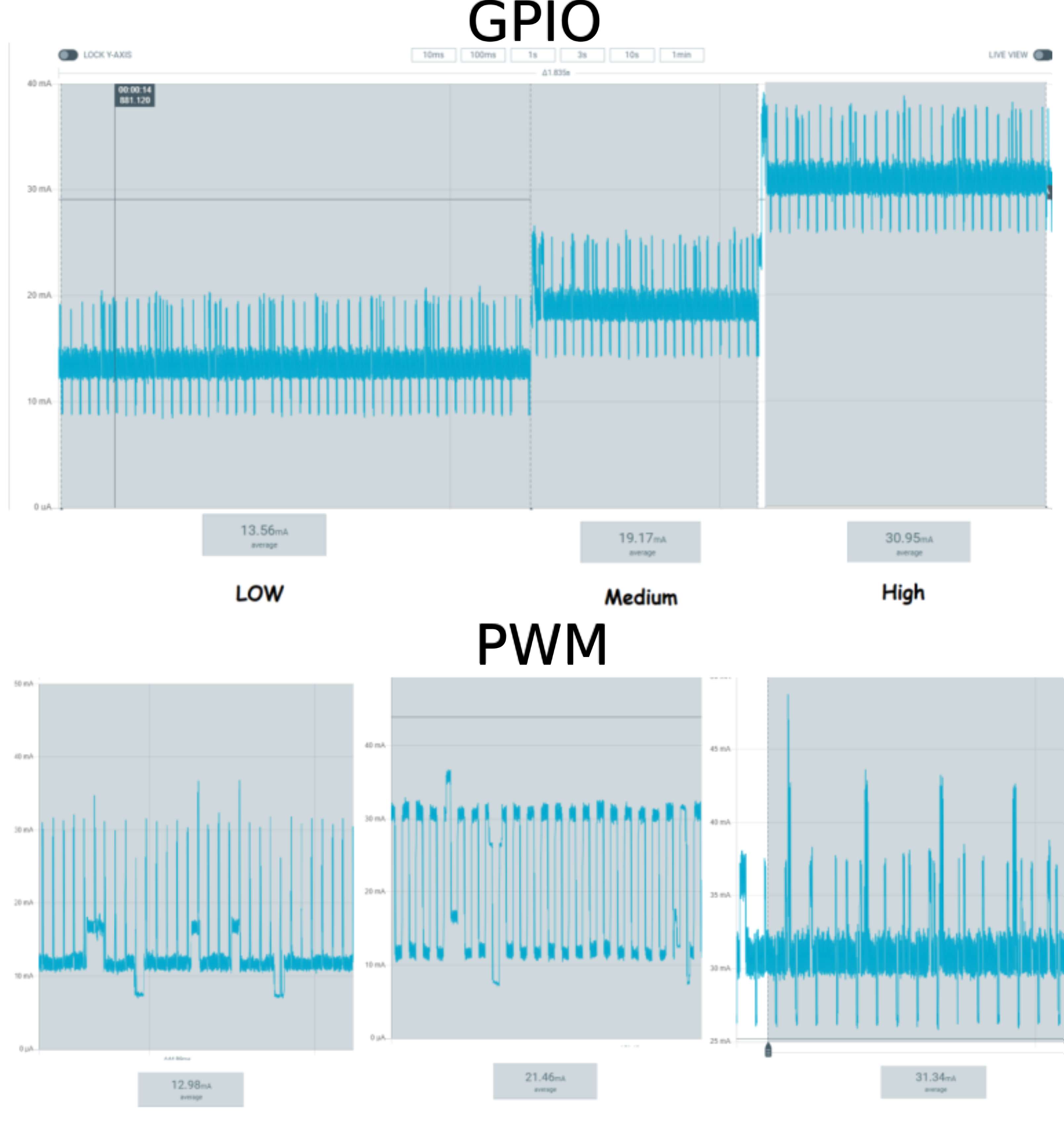
@geekbozu did a measurement on nrf PPK2. It seems that values are quite similar. However I must optically verify that PWM value for low/med looks the same as the gpio settings. Then we might measure again. However in high the pwm duty cycle is 100% on, and there is 0.4 mA error based on some spikes the FreeRTOS/BLE is doing between gpio/pwm mode. So I'm not sure we could compare gpio and pwm perfectly, there will be like 0.5ma measurement error at least.
|
Its always theoretically "more inefficient" even if it isn't a noticable difference and enabling the PWM peripheral probably uses some more power if I'm understanding these peripherals correctly.
We don't need to do that if we just control PWM on a single pin at a time. For the transition from low to medium for example it could just sweep the entire PWM range and end up at the non PWM medium brightness. This might actually end up being simpler and more straightforward in the code. There is also a way to set a PWM sequence in NRF, so the sweep can even be done automatically by it. Also if we use PWM for just one pin at a time, the range doesn't need to be the large 0-10000 as well. |
|
Hi @geekbozu, can you please measure the consumption of adf4979 ? I increased the PWM values for low/med so it perfectly matches the brightness with gpio pins. Please do at least two measurements because and select really the periodic area of current. The less irregularities of RTOS/BLE, the more precise measurements we get. |
|
Since the consumption is practically static and I want average, then UT61E is enough to get some idea. Battery voltage 3.7V So the PWM adds around 0.5 mA mostly in switching losses, which is around 3.5% of consumption on medium level only when the screen is on. I do not see this increase critical, since you have to also calculate how often your screen is on during the whole day. I don't wan't to argue and loose time with this debate, so you, community and JF002 will decide. I'm good at low level programming, so I thought I add PWM dimming for someone, who is better in high-programming and we would improve InfiniTime together. That's it. What I think would improve consumption much more is 1.3 mA consumption in standby. Not sure if it is FreeRTOS/MCU or static consumption by some chips/parts. We use NRF52832 & 840 and we design battery IoT products running with Softdevice, FreeRTOS & BLE advertising around 400 uA. Just wanted to put this in context of the whole image of consumption. So if you would like to do PWMing only during transitions, let it be (I added |
|
So some notes about the numbers I have: an ~3mA offset must be removed for the active debug interface peripheral. . The first plots were taken with a broken BT instance PER the BLE bug JF is chasing, So there is about a 400uA offset between them as there was no advertising occurring during the static resistor test, where the PWM there was. This puts them at about a 50uA difference, save medium. Which as we know is a different brightness in the data above. All of this said, I do want PWM brightness because sometimes Full is to much and medium is too little... I feel like the extra losses here are worth the expense. Yes its more complicated, but it services everyone's needs. Allows better customization, while retaining efficiency where desired. |
|
Having a 0-100% selectable range would introduce problems with the UI. How about doubling the number of steps and having every other use PWM? This would keep everything simple in the UI and the brightness button could still be used as is. The brightness range isn't that wide so while three steps are already enough for most people, six should be plenty for everyone. This is what the steps could be. Maybe the duty cycle has to be different to follow a more exponential curve.
EDIT: This way the power efficiency also won't be as big of a problem. On brightness 5, the power consumption is between 4 and 6 as it should be without even considering PWM. |
It would be a bit more difficult to implement for sure, making "the resistor values "Sticky"" could be done with just coloring the slider a different colour when it's "good" (so green).
I'm not so sure. I constantly battle designers who thought the same, often with the difference between the lowest and zero being too large.
Yes, https://training.ti.com/linear-vs-exponential-dimming-lcds this should certainly be taken into account for a good user experience. |
|
hi |
|
@lman0 Hi, this PR is ready to be used. The goal was to add hardware and low-level code to have the same functionality as before, so others can build on this PR and create smooth transitions and more backlight levels, like you said. |
|
I'll close this because it doesn't add or fix anything by itself. |
Added PWM backlight support with 8 MHz clock and 0-10000 range it makes 712 Hz.
I choosed 10000 to be nice round number, but we can have up to 32767 (15bit counter), but then we might increase the PWM frequency to 16 MHz but then we get lower pwm frequency 488 Hz which might be low and possible to see (I'm really sensitive to PWM LEDs on some cars which other people cannot see :) )
PWM range 0-10000 is something like 13-14 bits, which gives us smooth transitions even in lower intensity area.
https://github.com/JF002/InfiniTime/compare/develop...hubmartin:pwm-backlight?expand=1#diff-c94d14f480d7dc83cdb112ff049a32c127fb99816b700deddcc7dd093a48c869R31
Hope that someone will improve this and incorporate smooth transitions for on/off and dimming. :) 👍